
How a Relay Launch Controller Works
Rocket Information you can USE!
Relay Launch Controller
How does a relay launch controller work?
A relay launch controller is desirable because you can have the main current/voltage source close to the igniter, right by the launch pad, so there is little current loss when it is time to light the igniter(s). A relay is nothing more than an electronic switch. Instead of flipping or pressing a switch manually, a small electromagnet in the relay does it for us. This switch then sends 12 volts, from a battery sitting right at the launch pad, to our igniter.Let's get to the explanation
This design of a relay launch controller uses a small 9-volt battery in the hand unit for continuity and to trigger the switch on the relay for launch. Upon triggering the relay switch, 12 volts from the more powerful battery at the launch pad, is directed to the igniter, setting it off and thereby igniting the rocket motor. In the three diagrams below, you will see exactly how this works.Figure 1 - Safe Mode
Observe the schematic below. When the launch controller is in safe mode there it no current running through the circuit. On the left, you can see (circled in red) that both the safety key and the launch push-button are open, disabling the 9-volt battery, and on the right, the relay is in it's "normal" mode (the red lines) so the 12-volt battery not connected to the circuit.This is the state the launch controller should be in when we are preparing our rocket for launch at the pad.
Safety Note - To totally prevent premature rocket motor ignition, connect the launch controller leads to the igniter BEFORE inserting the igniter into the rocket motor. Then, in the off chance something is faulty and the igniter leads are live, the igniter will light BEFORE you insert it.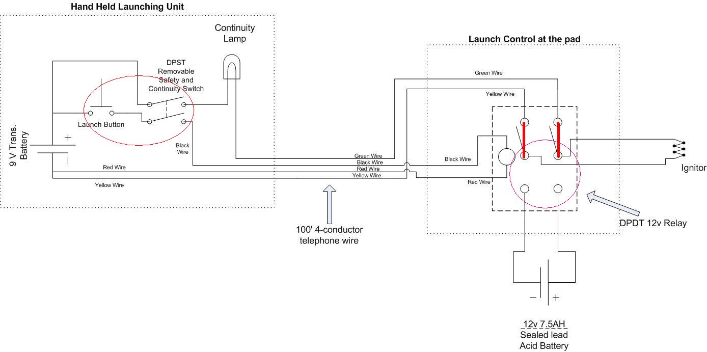
Figure 1
Figure 2 - Continuity Check Mode
Looking at figure 2 below, this is the state the launch controller is in when we are ready for launch. After inserting the igniter in the motor, and turning on the safety switch, the current from the 9-volt battery travels the path of the blue line while transversing the closed safety switch and relay (circled in red). The "launch" button (circled) is not depressed so the electrical current flows around it through the continuity lamp. The relay is still in it's "normal" mode allowing current to flow through it from the 9-volt battery to the igniter, thus completing the circuit and signaling continuity via the lamp. If there is proper continuity the lamp will light and we are ready to go for launch.
Figure 2
Figure 3 - Launch Mode
When the countdown reaches zero, we press the launch button (circled in green) completing the circuit (the safety key is still on) to the relay switch. What happens then is that we bypass the continuity lamp and send power (from the 9v) directly to the relay (see the blue path below). The relay coil (circled in purple) is then engaged, triggering the electronic switch in the relay. When the relay switch is "flipped", it competes the circuit (circled in brown) and directs power from the 12-volt battery directly to the igniter. This electricity flow is the green line. When the 12-volts from the battery at the pad reaches the igniter, the igniter fires immediately. Once the igniter lights, it ignites the rocket motor and then breaks the circuit, but by then the rocket is on it's way.
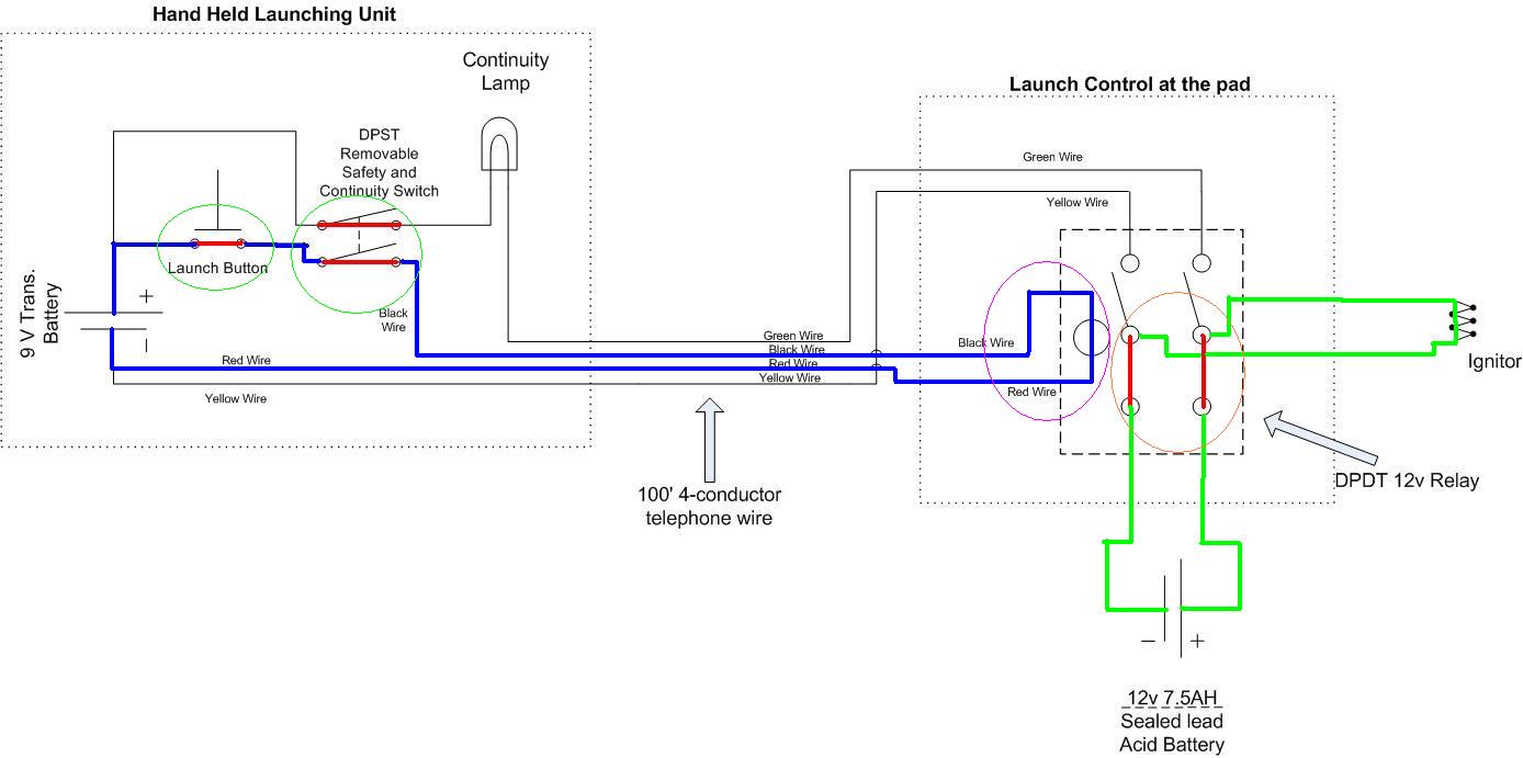
Figure 3
